Category Archives: Fabrication

“Amplifier”

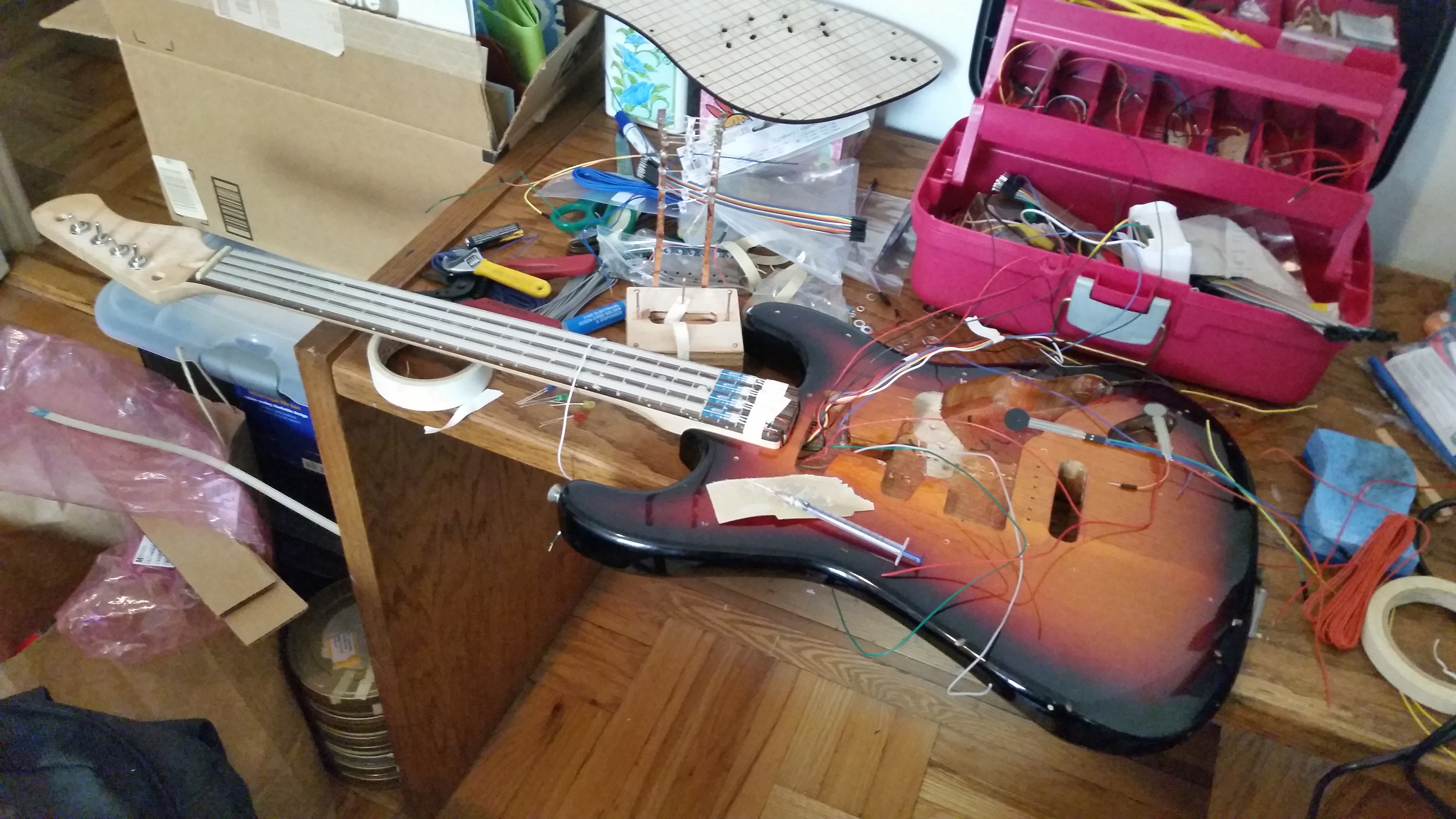
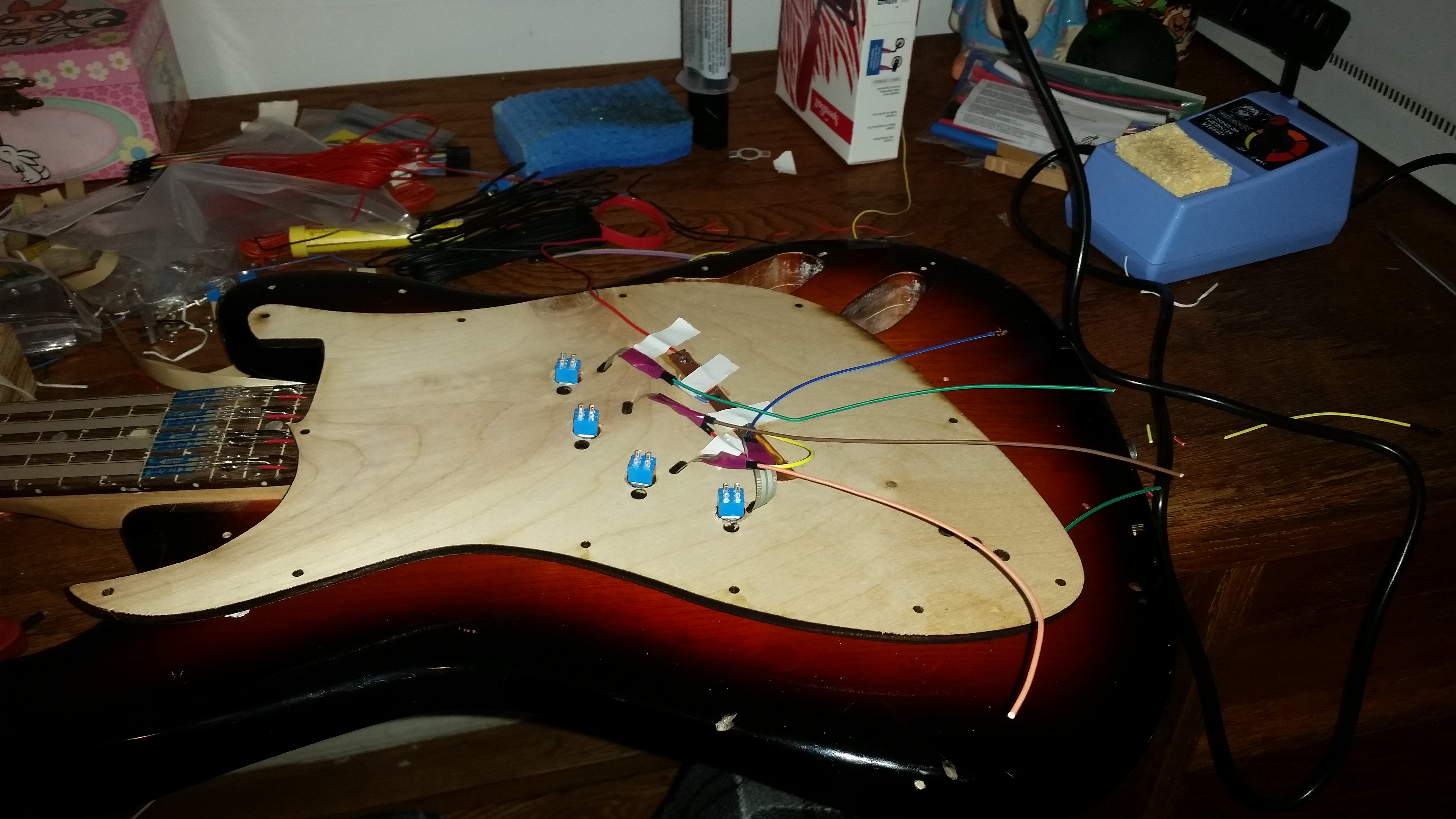
For my final project for fabrication, I decided to build an “amp” to go with the guitar I made earlier, to hold and display the output portion of my final Physical Computing project – four walkmen, four sets of computer speakers, and a really big, ugly circuit. When I initially presented it, all the components were staged on a board:

2015-12-14 09.56.54

Pretty good for transport, not so much for display, and very little flair.

My idea was to make something that used ideas from old stereos and musical equipment but updated and tweaked them. I decided I would build a wooden cabinet, and crown it with a metal grille/enclosure that would somewhat obscure the circuit while allowing the other elements to be displayed more prominently.

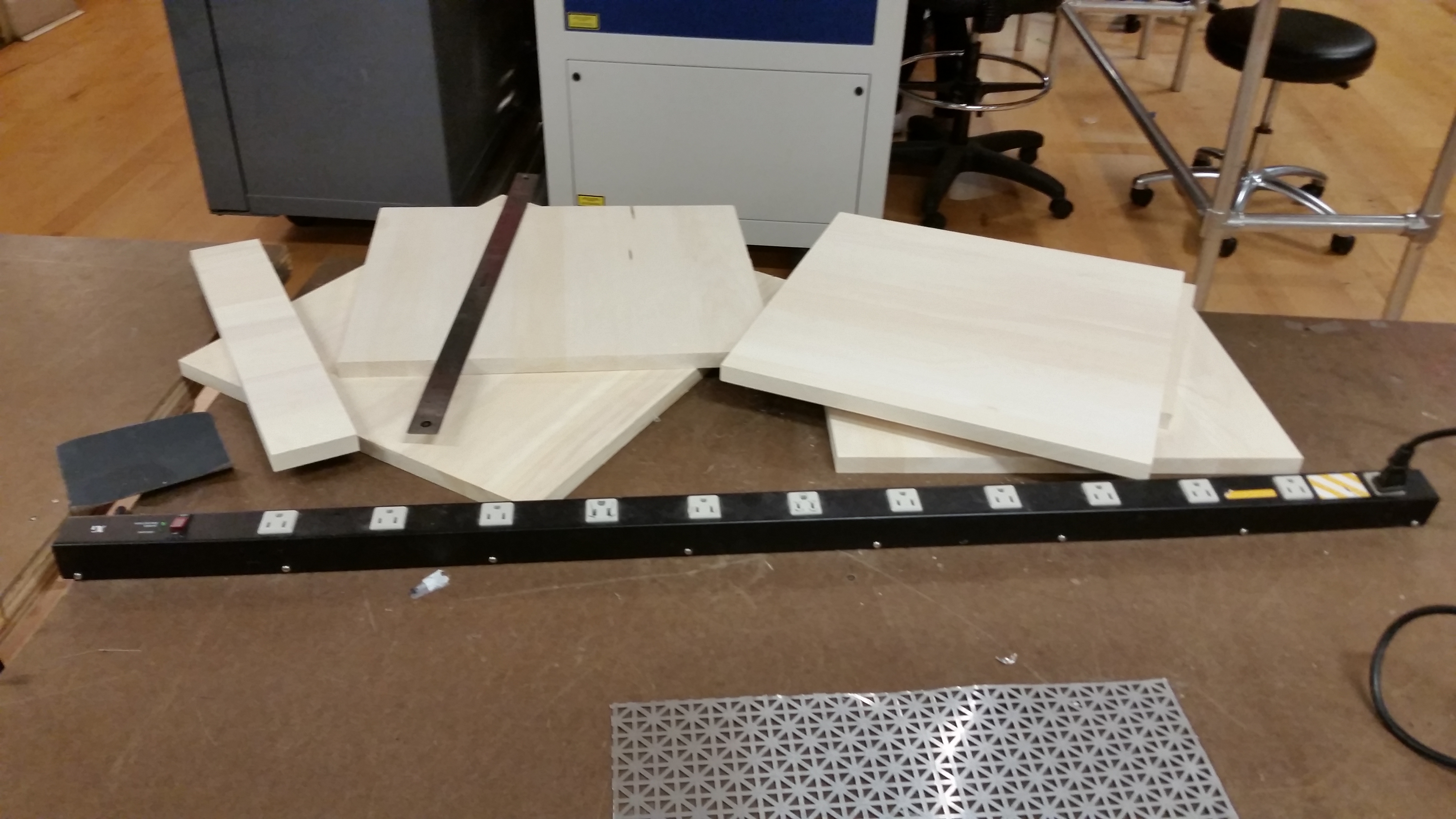
I began with a trip to Lowe’s. I wanted to avoid using plywood if possible, but I knew that, with the dimensions of the cabinet being what they are (~18 x 18 x 21), it would be very difficult to find (and even more difficult to afford) solid boards wide enough. I found some edge-glued aspen panels that were quite reasonable, and bought enough to do the job. I also picked up a sheet of union-jack decorative aluminum radiator cover (my new standard, apparently), “mission oak” stain, some aluminum rod and various bits of hardware.

My first step on the actual project was cutting the panels to size using the panel saw:

2015-12-12 13.00.32

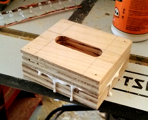
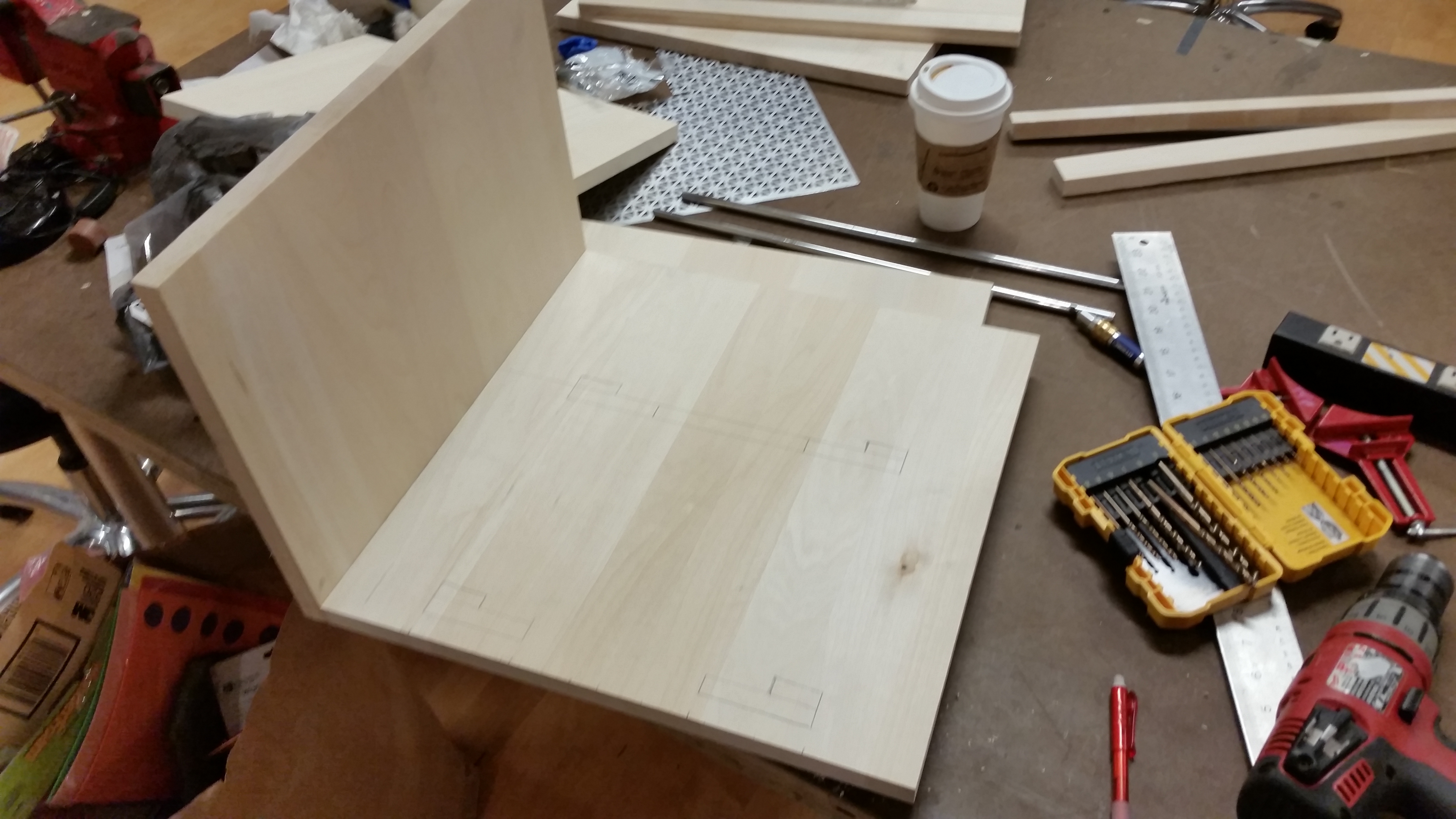
I then corner-clamped, screwed and glued the panels together to make the body of the cabinet.

2015-12-12 16.22.36

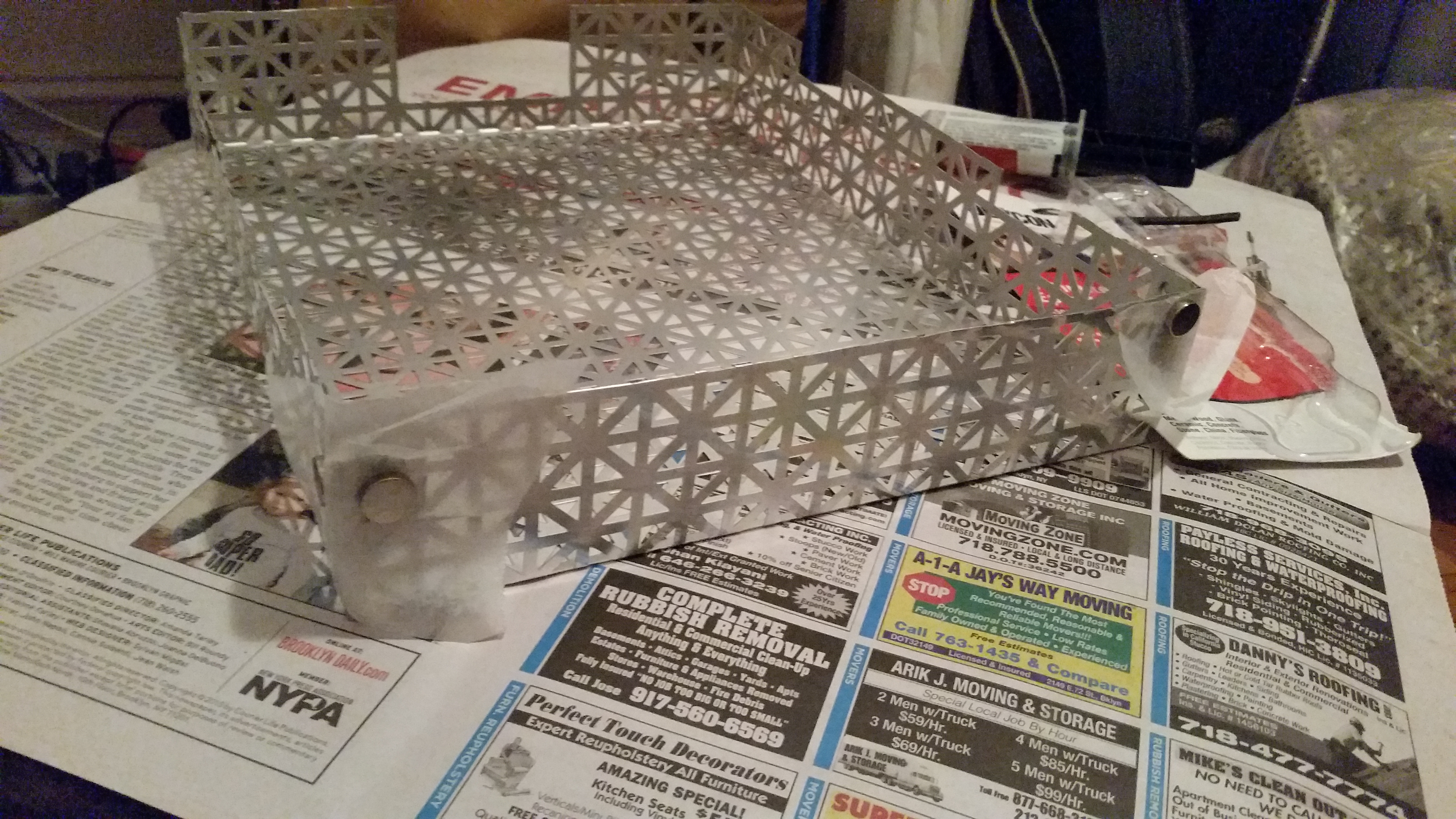
Once I had accomplished that, I cut out and bent the aluminum for the top, using the electric nibbler (amazing!) a regular nibbler (equally amazing!) and the press brake.

I then cut down my aluminum rod and polished it with the bench grinder and tripoli compound. I was amazed at how easily the aluminum took a shine (my previous polishing experiences having been with 304 stainless and copper plates), and then amazed at how many deep nicks and scratches were on the rod from its time on the shelf at Lowe’s. In retrospect, I should not have been amazed. Oh well, it’s still shiny.

I then got the whole thing assembled (using corner braces to attach the middle shelf) and filled my screw-holes with wood filler.

2015-12-13 07.06.10

2015-12-13 09.02.31

Next step was to sand and stain. I sanded everything down, treated the wood with pre-stain, and brushed on the stain.

I then needed to stabilize the aluminum box for the top. I used corner braces and 5-minute epoxy, holding the corners in place with magnets while the epoxy set.

2015-12-13 22.31.18

And then I temporarily removed the middle shelf and attached a piece of fabric to the back wall with upholstery tacks, both to add visual interest (and provide another “amp” element) and to cover the rather unsightly holes I had to bore to allow the cords of the speakers to pass through into the back (where the power supply will go). Then I drove the aluminum rods into position, and it was done!

2015-12-14 09.56.26

With the electronics installed, it looks like this:

2015-12-14 10.24.00 2015-12-14 10.24.08 2015-12-14 10.24.31

All in all, I’m pretty happy with it. There are definitely things I would build differently if I had to make it again, but it’s a definite improvement over the board.

Mood Lighting

This week, I decided to make a lampshade from fabric and aluminum.

I purchased a sheet of decorative punched aluminum (radiator cover, etc.), a wooden disc, a ceramic lamp base, a package of cheesecloth and a bottle of Aleene’s Fabric Stiffener and Draping Liquid. I cut the aluminum to size and drilled several holes at each end for rivets.

Step one: bend the metal –

2015-12-05 10.29.45

Step two: rivet –

2015-12-06 13.48.31

Step three: soak cheesecloth in fabric stiffener and drape –

2015-12-06 14.01.13

2015-12-06 14.22.12

Step four: wire lamp (repurposing an old extension cord) –

2015-12-07 11.12.28

Step five: attach lamp to base –

2015-12-07 11.19.22

Step six: let there be light!

2015-12-07 11.19.16

2015-12-07 11.18.30

All in all, I’m pretty happy with it. I really like the contrast of the chaotic/organic form of the fabric with the rigid geometry of the metal, especially as the metal is fairly well hidden when the light is off and comes as a bit of a surprise when it’s turned on. I think I’ll put it on an end table somewhere.


Enclosure

2015-11-24 21.47.092015-11-24 22.20.172015-11-25 01.01.492015-11-27 20.53.162015-11-28 12.11.282015-11-29 15.07.502015-11-29 15.49.172015-11-30 08.54.102015-11-30 14.16.402015-11-30 14.47.482015-11-30 15.58.162015-11-30 15.58.422015-11-30 15.59.362015-11-30 15.59.462015-11-30 16.00.57

One Picture Two Ways

2015-11-20 22.19.58

One of my bigger struggles at ITP has been my innate tendency towards Luddism. I know it’s crazy, and I know that the world moves forwards and not backwards (that’s why I’m at ITP, of course), but there’s an internal Andy Rooney sitting in the back of my head that uses words like “newfangled.” I can’t help it.

So I think, of all my colleagues, I might have been the least excited about developing a project for the laser cutter. But it is a tremendously useful tool, and the things it can do are amazing. I just have to keep telling myself that it is indeed a tool, wrought by human hands and minds, and not the advance guard of the robot takeover. Anyway, I digress.

This week, I decided to build on an idea I’ve been working with for a little while, etching photographs into metal. As a screen printer, when I’m given a photographic image to print (or any image with shading and tonality), the first step is to break it down into a halftone, a matrix of black and white dots. This is done easily enough in Photoshop, and then we can either print the black onto a light surface or the white onto a dark surface. And the surfaces and inks don’t have to be actually black and white, of course – as long as the relationship of dark to light is preserved, you get essentially the photo you started with.

But this presumes matte inks and surfaces, where the paper is always one color and the ink is always another. Metal, of course, can appear to be any color in any moment, depending on lighting and surroundings, and so the etched photographs I’ve made (using acid and a screenprinted resist, where the “background” is mirror-finished steel and the “foreground” is etch, or vice-versa) look “right” only part of the time. They also hearken back to Daguerreotypes, which were similarly metallic. It’s a mysterious and rather beautiful look.

My plan this time was to coat a couple of stainless steel plates with black and white spraypaint and etch the same photo into each, with the etch on the black inverted from the etch on the white.

StephMASTER

I chose a photo I took of my girlfriend at the beach a while back that I’ve always meant to do something with but hadn’t got around to actually using. It seemed like a good candidate, given that there are highlights and lowlights, and plenty of smooth grays, where the inherent confusion of the metallic surface can really shine. I broke it down into a 75-line halftone at 600 dpi, loaded it into Illustrator on the shop computers, and hit “print.”

2015-11-20 22.20.23

2015-11-20 22.21.08

The only real issue I had was with the dithering. Obviously, in order for the laser to etch a surface, it needs to know where to etch and where not to, and it’s a binary process (i.e. you can’t get a weak etch on a lightly toned spot, but only 100% or 0% etch), exactly like screenprinting. In order to accomplish this, the software employs a dither (a halftone filter, either regular or stochastic) that can’t be defeated. I had already halftoned my image in Photoshop, in anticipation of needing pure blacks and whites for the machine, but I couldn’t get it not to re-dither my work. After a little experimentation, though, I found a setting that preserved my halftone pretty well.

2015-11-20 22.22.30

Also, I discovered just how dependent laser etching is on the thickness of the surface being etched. When I was preparing the white plate, the paint I was using had some problems – it started coming out in hideous chunks. Eventually, after lots of shaking, and spraying with the can inverted, I got it to coat more or less evenly, but when I etched the plate, there were some speckles in the image that I’m certain were originally droplets in the paint. They look really interesting (and add a random/human touch) but if I were going for perfection, I would have been in trouble.

Speckles

Then it was time to mount the photos together for presentation. I had thought about maybe using cloth or a folded card, again as a vague throwback to 19th- and early-20th-century portraits, but then, as I was looking around my shop for materials, I found the board I had been using to spray the plates on, with a really interesting looking outline of a plate in white paint. I cut out a chunk of the right size, mounted the plates with 2-part epoxy, and voila!

PhotosFINAL

Letting it Slide

For my final project in Physical Computing, I’ve been wavering back and forth over whether to use four slide whistles or four walkmen to play music. I’ve wanted very badly to use slide whistles, but have been nervous about the number of engineering questions that would raise. So I decided this week to construct four (well, five in this case) slide whistles and see what it was like to work with them.

I began by finding an Instructable online (http://www.instructables.com/id/Simple-PVC-Whistle/) and running to Home Depot to gather materials. In my possible p-comp project, I would need to make tones lower than are usual for a slide whistle, so figured that it would be best to use a wider pipe (why, I’m not quite sure… visions of church organs perhaps). I bought 1″ and 1.25″ PVC pipe, and corresponding dowels. Nothing fit snugly, but I figured I could shim what I needed to with masking tape.

Once I was back in my studio, I experimentally cut a notch in the 1″ pipe using a jigsaw, inserted a shimmed and shaved piece of dowel to direct the air, and blew through it.

2015-11-15 17.26.30

Nothing. I inserted another dowel into the other end. Nothing. I pulled out the dowel and wrapped it with masking tape, and put it back inside, fairly snug. I blew again. A tone! Success!!

But not a great tone. I cut off the end of the pipe, watched a few more videos online and deduced that the narrower the angle of the blade of the notch (the thing that’s making the sound when you blow across it) the stronger the note I would get. I finally made a notch I liked, and drew a gauge on a piece of masking tape to let me know how big to make the first cut.

2015-11-15 16.34.58

Looking at how much pipe I had left, I figured I would make the whistloes 17″ long, which would give me enough material for one extra in case I made a mistake. I would cut my notch, insert the taped dowel, check that the note sounded, and then make the final cut. Working this way, I obtained five more-or-less even whistle bodies.

2015-11-15 16.46.37

I then sanded them down (one of my pipes was in really gnarly shape), masked off the sensitive areas and spraypainted them red, using a very impromptu stand I made out of chunks of dowel and a spare piece of plywood.

After a second coat of paint, it was time to unmask and add in the slide, and that’s where things got  problematic. The tape-wrapped dowel I had been using to test the whistles had worked okay but not great – I had assumed I would be able to fine-tune a usable slide using tape, or rubber bands, or something. But everything I tried either got stuck or let air through, or (nearly always) both.

(It was around this time that I remembered back to our first class, and to the observation that “straight” and “round” are really just concepts, never exampled in the real world. Feeling a slide travel the different widths of a 17″ length of PVC definitely reinforced that.)

The problem, then, was to find something that could be mounted to the slide that would be both easily movable and, at any given point, essentially airtight. The fellow at the plumbing supply shop by my work suggested cutting a groove in the side of a piece of dowel and mounting an o-ring, which was a brilliant idea, but the hard rubber and narrow profile didn’t allow enough compensation in wider areas of pipe, while it still threatened to get stuck in narrower areas.

In the end, I went to Dick Blick and bought everything squishy I could find. After some experimentation, it turned out that children’s craft foam, hot-glued on top of a whittled plug, gave the closest approximation  of what I was looking for. Still not perfect (or near it) but serviceable.


2015-11-16 16.23.11 2015-11-16 16.28.31

I mounted the slides to pieces of heavy aluminum armature wire and closed off the ends with fender washers.

20151116_170528

20151116_170455

In the end, these would need a few tweaks before they would really be playable instruments. Dowel and foam isn’t really a good slider (to say nothing of the longevity of such a contraption) – I would want to research further and really find out the right solution. The armature wire is too soft for a slide fixture, the notches aren’t totally uniform… there are definitely ragged edges. But I know more about them than I did before I made one.

And my p-comp project is now officially, finally, not going to involve slide whistles.


Flashlight!

Everybody’s got a little light, under the sun. – Parliament

For weeks I have been intending to buy a gooseneck lamp. My apartment, though wonderful in other ways, has possibly the dimmest lighting of any dwelling I’ve ever set foot in. Which is fine for general living (and who wants to live in a workshop or operating theater anyway?), but not for taking apart tiny electronics and soldering them, which I’ve been doing rather a lot of lately. So I keep meaning to buy a gooseneck lamp, but haven’t had the chance to actually do it.

Enter the flashlight assignment – I figured why not make a portable, flexible lamp that could double as a flashlight? Two birds, one stone, and no more strained eyes, stripped nano-screws and burnt components.

A couple of years ago, I made a lamp for another project, a clear-resin cast of an ostrich egg with an embedded LED array made from strips of heavy copper foil with LEDs soldered across them.

EggLampLitLightsOn

I really liked how visible the electronics were – not wires hidden in manufactured cases, but raw copper and blobs of solder, right out in the open. I decided to build on that framework for my lamp/flashlight.

My initial thought was to build something like this – two wooden “feet” with the lighting element sandwiched in between. I would use a single lithium-ion battery, which yields twice the voltage of a normal disposable or rechargeable cell, and so incorporate the battery prominently into the design.

LampSketch

As luck would have it, I had to go up to Massachusetts to see my family this weekend. My stepfather is almost single-handedly renovating his and my mother’s house, and has a full wood shop and piles of excellent wood scraps, as well as lots of good advice and guidance.

I began by shearing some strips of the heavy copper foil I had used to make the egg lamp. I quickly realized that they weren’t quite heavy enough to stand up on their own, but folded in half lengthwise, they became quite sturdy. They also became a little lumpy, but I kind of liked the rustic look. It fit in well with my concepts for this project, such as they were – utility, visible functionality, and making good use of what was at hand.

Next, I found a couple of nice small offcuts of maple plywood, matched in size, to make the base. My stepfather showed me how to use the router to carve out a channel for the battery, and I harvested a negative-terminal spring from an old Walkman I’ve been using for another project. SpadeBitWork

BatteryIn

Then it was time to make the actual light. I had been agonizing a little bit over how to run the LEDs. Technically, one is never supposed to put multiple LEDs in parallel without each having its own resistor, since it’s possible that one diode could end up running all the current through itself and burning out. In practice I’ve never seen this happen, but I figured it was perhaps best to do it the right way.

The only trouble there is that resistors seem to come in one size that is easy enough to solder to a wire or sheet but is too big to work aesthetically, and another that is petite and svelte but has no wires and is only really meant to be used on circuit boards. I chose the latter (I had a bunch of both on hand from the egg), and used masking tape to line them up to the foil as best I could. Not a precise process at all, and things became, er, a little more rustic…

SolderTape

After I soldered both sides as best I could, it was time to build the actual lamp. My stepdad had a box of very nice-looking copper nails, which I thought would work well with the other copper, and could serve both as a structural element and an electronic one. I decided, rather than have the base spread out with the lighting tower in between, to stack the two pieces of wood and nail the light to the back. I could then nail in the terminals for the positive and negative connection (as well as a raw-canvas “ribbon” to lift the battery out) and run thin wires around the corresponding nails to transmit power. I also drilled pilot holes (at my stepfather’s suggestion), and nailed the two pieces of wood together to secure them after gluing.

Glue

When I got back to Brooklyn, I finished assembling the lamp, nailed in the electronics and ran the wires.

Assembled

I also added dots of hot glue over the solder joints, which were very fragile, especially at the tiny resistors. Not my first choice for aesthetics, but having the glue take the mechanical stress allowed me to bend the lamp much more freely, which was, after all, the point of making it in the first place.

LampBentBack

LampStraight

All in all, I’m fairly pleased with it. It’s definitely rough in places that I wish weren’t quite so rough, but it’s handsome, and, more importantly, useful.